SUBSCRIBE To Our Mail List To Get This Article In PDF
Once upon a time, I worked for a power systems integrator. Our company engineered, manufactured, assembled, and tested emergency power systems for data centers around the globe.
In our world, the uninterruptible power system (UPS) was the centerpiece of the emergency power system; everything else supported the UPS. If you asked any of us about the automatic transfer switches (ATS), we would have told you that it was a simple unintelligent device intended to transfer between the utility or normal source and the emergency or backup generator to support the UPS.
The truth is that nothing else will function without the ATS.
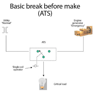
The open-transition ATS is designed to monitor its normal source of power, usually the incoming utility. When the normal source is interrupted, the ATS control panel sends a start signal to the backup generators, samples the power level once the engine generator starts, and transfers to the alternate (emergency) source. The ATS will remain connected to the emergency power source for the duration of the utility outage. When commercial power resumes, the ATS controls will confirm the viability of that source and re-transfer to the normal source following an adjustable time delay to ensure source stability. This return transfer occurs between two live sources that are not synchronized. For many applications such as UPS systems and inductive motor loads, it is desirable to transfer “in sync” utilizing a passive sync check device. This reduces the negative dynamic effects of an out-of-phase transfer.
The open transition-ATS with bypass isolation combines all of the standard ATS features with a second manual transfer device. This manual power transfer device is connected in parallel and interlocked with the automatic switching mechanism. Under normal operating conditions, this “bypass/isolation” mechanism provides a means to bypass the automatic power transfer device if there is an operational problem or for routine maintenance. This device is fully rated and capable of making a manual transfer between the “normal” and “emergency” source. Once the bypass/isolation device has been connected and transferred to the appropriate source, the automatic power switching mechanism may be placed in one of two positions.
Figure 2. The isolation bypass ATS provides functionality useful for maintaining the equipment while retaining power reliability.
Position 1 is the test position. In this position, the main power poles of the automatic power switching device are disconnected; however, control power is still available so that the ATS may be tested by qualified maintenance personnel equipped with appropriate personal protective equipment in accordance with the hazard level identified as defined by NFPA 70E.
Position 2 is the isolate position. In this position the ATS mechanism is completely disconnected from all power and may be completely removed for invasive maintenance and repair.
Some things to consider:-
- Most manufacturers provide a variety of accessories to fine tune the device to the application.
- The power transfer switch must be coordinated with other system components, no matter what type you use. For example, the speed of the transfer may present a problem for a UPS, variable-frequency drive, or other downstream load. In this case a pre-signal from the ATS may be desirable. This may be a contact closure or opening prior to the actual transfer allowing for a connected device to revert to a controlled state or shut down prior to the transfer. Following transfer, the action is reversed and all system components return to normal operation. you may wish to force a UPS to its battery until the transfer is complete.
- The coordination of set-points in the system can be a major issue. Take the voltage drop out or lowest acceptable value for example. Consider what would happen if the ATS had a lower drop out value programmed into the ATS controls than the UPS. In a brownout, the UPS might go to its battery while the ATS would remain connected to a low utility source because its critical setpoint had not been reached. This also means the engine generators would never start. In the end result the UPS would run out of battery backup and crash.
- There may also be interfaces with other building systems depending on the circumstances or local building regulations. In some cases, you may wish to signal all elevators to return to the ground floor in the event of a power failure. In this case a pre-signal from the ATS could be interfaced with the elevator controls for that purpose.
SUBSCRIBE To Our Mail List To Get This Article In PDF


